| Displacement cc/rev: | 21 - 115.9 |
| Gear Widths: | 1/2" - 2.3/4" |
| Max PSI / BAR: | 2500 / 172 |
| RPM: | 400 - 2000 |


FD5000 / 5100 Series
FD5000 / 5100 Series
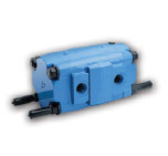
FD5000 / 5100 Function
The main function of the PERMCO FD5000 / 5100 Flow Divider, is to accept flow then divide it equally or unequally. Alternatively it can combine flow in the return direction and distribute pressure based on your requirements.
The main benefits of using a PERMCO flow divider in your hydraulic system is to:
- Simplify circuitry.
- Increase life of components.
The above will achieve a reduction in costs.
Basic Sizing Requirements
The most efficient gear widths are 1” or larger.
The most efficient speed of the PERMCO flow dividers is between 700 – 1400 RPM.
Units with ALL gear widths of ½” and ¾” should be avoided.
EXAMPLES: Units with ½” gears would work best with another section of a least 1-1/2″.
Units with ¾” gears would work best with another section of a least 1-1/4″.
In three section units or larger, it is good practice to position the inlet port nearest the largest gear section. It is also recommended that the largest gear section be placed in the centre of the unit.
For applications where speeds are below 500 RPM or above 1400 RPM, and/or where pressure across the unit may exceed 2000 PSI (138 Bar) for the 5000 series / 2500 PSI (172 BAR) for the 5100 series, please CONTACT US to discuss further.
How to Select Your Flow Divider
To select your PERMCO flow divider, this procedure should be followed:
For equal flow division:
Select a gear width greater than one (1″) inch from the charts keeping the speed between about 700 RPM and 1400 RPM.
For unequal flow division use the following procedure:
- Determine the outlet flow required for each leg of the hydraulic circuit.
- Use charts below to select a series and gear width for the leg with the greatest flow (keeping gear widths greater than one (1″) inch).
- Move straight up the chart to select the other gear widths by choosing gear widths with the closest flow at the same RPM.
- Check the actual flow for each section to determine if acceptable using the following formula.
GEAR WIDTH / (TOTAL GEAR WIDTH) X TOTAL
FLOW = FLOW FOR SECTION - If the flows are not acceptable, repeat from step (2) by choosing a different gear width or moving to a chart in another series.
FD5000 / 5100 Flow Chart

Flow Divider Assembly Coding Example

FD5000 / 5100 Dimensions
